|
|
The Best Laid Plans....
|
|
|
|
The Best Laid Plans....
|
|
If you've been following my discussion and outline, you're waiting for me to obtain an inverter to connect to the Prius. In the good news/bad news vein, I still haven't been able to find an inverter manufacturer to supply exactly what I'm looking for. But, as it turns out, there's a possibly better solution, and it's built into the name of this web site. Our requirement is to take the 210-230VDC available from the Prius and convert it to 230VAC for household use. I kept thinking "inverter... inverter... inverter..." as a standalone device, without considering the most common (by far) use of inverters: the ordinary computer UPS. My reason for ignoring this obvious possibility was the ingrained (and totally incorrect) notion that these UPS units ran on low-voltage batteries.
I'm not an IT person and can be forgiven this solecism, of which I was disabused by Michael Grace's research. A consumer-grade UPS will typically have a 6 or 12V battery. Somewhat larger ones may run on 24V or even 48V. In fact I bought a 2KVA UPS some years ago that had four 12V batteries in series. It turns out that serious computer room UPS units indeed do employ high voltage batteries. What high voltage? Typically 240V. Sound familiar? Suddenly the common UPS went from a nonstarter to the inverter of choice. The benefits:
Readily available and cheap
Power requirement commensurate with Prius battery
Built-in "transfer switch" - no absolute requirement to install one since that's part of the UPS product definition
Readily available and cheap
What do I mean by readily available? Many manufacturers make a UPS in the 5-10KW (7-15KVA) range. What do I mean by cheap? Can you say "eBay?" A single search turned up a small handful of units, including a Lucent 12KVA/8KW UPS that not only seemed ideal but was located a short drive away. They tend to be heavy due to the batteries, so finding one locally was a boon.
Researching the specifications indicated a potential problem: The Lucent UPS standard battery package uses four trays of ten 12V batteries, for a nominal voltage of 120V per tray, or 240V (in series-parallel connection) for normal operation. The operating voltage is somewhat higher, typically 250-260VDC, just as the Prius normally operates at 10-30V higher than the nominal battery voltage. A UPS will charge its internal battery during AC input operation, and then discharge it when called upon to provide power. When the internal battery voltage drops below a threshold, the UPS will shut itself (and attached load) off to protect the batteries, which by that point will have only a small percentage of capacity available at the shutdown voltage. But if the normal UPS shutdown voltage is higher than the minimum voltage that the Prius provides, the UPS will not operate from the Prius battery, an obvious and essentially fatal problem for this project. Fortunately, the particular UPS I obtained has the facility for adjusting the minimum acceptable battery voltage, and the lowest voltage selectable was about 200V. The Prius, according to my experiments, never dropped below about 210V. Accordingly, with a modest check and a surfeit of glee, I purchased the UPS.
|
This is the UPS control panel. Among the many status "meters"
available are the AC and DC input and output voltages, and the battery
state of charge.
All this info is available to a computer connected to the RS-232 jack in the rear. Maybe I'll put it on the web if I get a chance... |
||||||||
 |
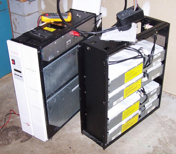
Here is the UPS and its battery cabinet. In the cabinet are
four trays of ten batteries, each 12 volts. These are similar to
the batteries used in small "consumer" UPS units, so you can see that
this unit has a capacity nominally 40 times greater. The bright red connector on the right side of the UPS cabinet connects the battery cabinet to the UPS. The interesting thing about this connector is that it mates by pressure only - no twisting or locking. It can be removed just by pulling. It's a candidate for the Prius connector as well. |
||||||||
 |
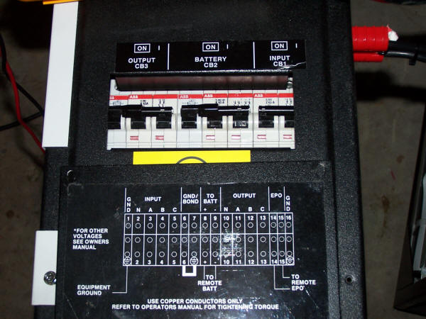
This is the top view of the UPS with the cover up. There are
three breakers:
Input, The terminal block diagram is normally on the rear of the unit, but I put it here for the photo.
|
||||||||
 |
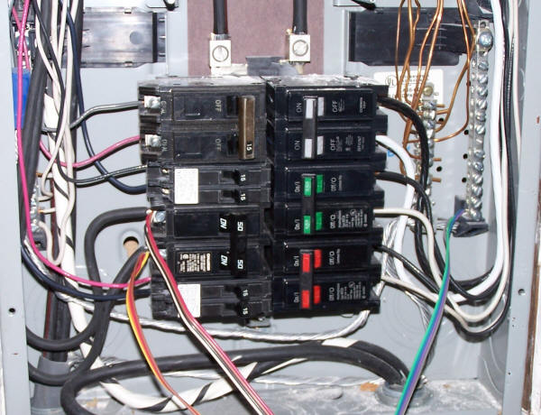
The brightly colored ribbon cables are a temporary connection to my
breaker box to test the system. I disconnected it shortly after
taking the photo, and will have a licensed electrician do the actual
installation with real, approved wiring.
The wires are connected in parallel with the 50 amp circuit powering an electric stove. Of course the UPS needs its own 50 or 60 amp breaker when properly installed.
|
||||||||
|
This monster 50-amp, 230V plug and socket used to connect the UPS to
the incoming electric service. The 50-amp breaker is on the right.
This is a detail of the 50 amp plug. If it weren't for eBay and Home Depot this project would be nowhere. |